(For older revisions check ILSE Build Instructions for Revision 1-3 )
Distributor for this module is Befaco. You can get it as well from Schneidersladen, Exploding Shed. Or directly from our shop.
This manual in a printer friendly format: Ilse_REV4_Assembly_Manual.pdf (1.4 MB)
This manual has been written taking into account the common issues that we often find people experience in our workshops. The order in which the components are placed on the board is meant to make assembly as easy as possible.
Some steps are not obvious, so even if you’re an experienced DIYer please read the steps thoroughly before starting.
If this is your first project, please read this short post before you start assembling the kit:
Use our iBOM
https://chairaudio.github.io/ILSE/REV4.html
It can help you with the build.
iBOM beware: Please go to the iBOM settings and select “Mark when checked placed”. The line in the table where the mouse pointer hovers over will highlight the parts on the PCB. Pitfall warning: Your screen goes into power saving, you wiggle the mouse to wake it up, mouse pointer now is over the wrong line, you continue soldering the components into the wrong spot. To avoid that, move the mouse to the right side of the screen where the PCB is and use the arrow keys to navigate the lines with the parts.
Please bend the legs of the components outwards (as shown below), so they don’t fall out of the board, then solder them. This is especially important for R1, R20, R22, and R34 so that none of the legs touch the potentiometer housing/stand-off on the front side of the board.

HAVE FUN!
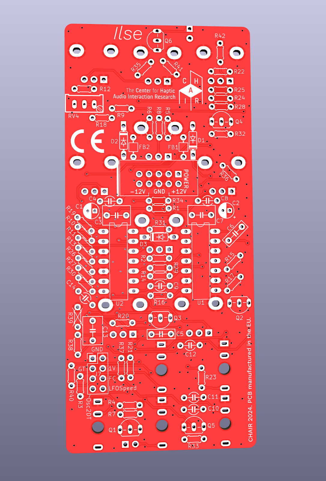
Start with the Back side (the one with our logo on it):
RESISTORS 
Color code can be difficult to identify, we strongly recommend to use a multimeter.
Useful are test leads from Parrot Invent.
Resistors have no polarity, it doesn’t matter which way you install them.
Suggested Mods for Eurorack use
If you are building Ilse for standalone use with a dual 9V battery power supply, use the resistors as listed in the original table below.
However, if you use Ilse in a Eurorack with a standard +/-12V supply, then we suggest the following modifications (highlighted in yellow) to the table below.
Less distortion
- Replace the 47k resistors on R26 and R27 with 220k ones.
Smaller range on main tuning knob
- Replace the 10k resistor on R1 with 0 ohms (a jumper, use a wire or a leg you cut off)
- Remove R2.
- Replace the 22k resistor on R13 with a 47k one.
| Qty | Value | Code | Name on PCB |
|---|---|---|---|
| 13 | 10k | Brown, black, black, red, brown | R1, R9, R19, R21, R22, R28, R29, R32, R33, R35, R36, R37, R40 |
| 12 | 100k | Brown, black, black, orange, brown | R4, R5, R7, R10, R12, R16, R17, R20, R23, R24, R30, R31 |
| 7 | 47k | Yellow, violet, black, red, brown | R3, R14, R15, R25, R26, R27, R34 |
| 2 | 68k | Blue, gray, black, red, brown | R2, R6 |
| 2 | 1.2k | Brown, red, black, brown, brown | R11, R18 |
| 2 | 2.2k | Red, Red, black, brown, brown | R41, R42 |
| 1 | 1M | Brown, black, black, yellow, brown | R8 |
| 1 | 22k | Red, red, black, red, brown | R13 |
| 1 | 4.7k | Yellow, violet, black, brown, brown | R38 |
DIODES (
( )
)
Solder the diodes observing their polarity. The black or white line on the diode must match with the white line on the diode symbol on the PCB silkscreen.
| Qty | Value | Name on PCB |
|---|---|---|
| 3 | 1N5817 | D1, D2, D3 |
FERRITE
To solder the two ferrite beads use a recycled resistor or diode leg passed through each ferrite and proceed as if it were a resistor. Ferrite beads don’t have polarity. These bad boys love to roll off the table and disappear. Be careful and secure them!
| Qty | Name on PCB |
|---|---|
| 2 | FB1, FB2 |
IC SOCKETS

Place the sockets (taking care to orientate them properly – the notch should match the image on the silkscreen) and solder them into their correct positions.
| Qty | Value | Name on PCB |
|---|---|---|
| 2 | Sockets only! | U1, U2 |
CERAMIC CAPACITORS
Identifying capacitors can be quite tricky. Codes stated are indicative, please take a look at this guide for help identifying capacitors: How to Read a Capacitor: 13 Steps (with Pictures) - wikiHow
| Qty | Value | Code | Name on PCB |
|---|---|---|---|
| 4 | 0.1µF | 104 (Disk) | C4, C8, C10, C11 |
| 3 | 1nF | 102 (Disk) | C5, C6, C12 (C5 and C6 have rectangular/brick marking on board) |
| 1 | 22pF | 220 (Disk) | C14 |
ELECTROLYTIC CAPACITORS
Values are written on the side of the capacitor. Mind their polarity (The long leg of the capacitor is the positive (+)).
| Qty | Value | Code | Name on PCB |
|---|---|---|---|
| 2 | 10µF | 10µF | C1, C2 |
POWER CONNECTOR
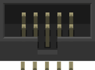
Solder the power connector at “J1” in the correct orientation according to the marking.
FILM CAPACITORS
Values are written on the top of the capacitor.
| Qty | Value | Code | Name on PCB |
|---|---|---|---|
| 1 | 0.22µF | 22k63 (Brick) | C9 (has a round/disk marking on the board) |
| 3 | 1µF | 1K63 (Brick) | C3, C7, C13 |
TRANSISTORS
The shape is better known as the TO-92 package. Used mostly for transistors but also many other devices. Watch polarity (orientation)!
| Qty | Value | Name on PCB |
|---|---|---|
| 3 | 2N3906 | Q1, Q2, Q3 |
| 3 | 2N3904 | Q4, Q5, Q6 (Q6: make sure between the two top pins is enough space for the potentiometer) |
JUMPER/PIN HEADERS
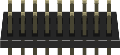
Place and solder the jumper. Double check they are straight.
| Qty | Value | Name on PCB |
|---|---|---|
| 1 | JP1 | JP1 |
| 1 | Shorting tin (JP2) | Put the shorting tin on the header JP1 to have the gate always open. (It’s recommended you start this way) Take the tin off if you need the gate. |
TRIMMER

Orient the trimmer so it matches the marking on the silkscreen.
| Qty | Value | Name on PCB |
|---|---|---|
| 1 | Single (3pin) 100kB | RV4 |
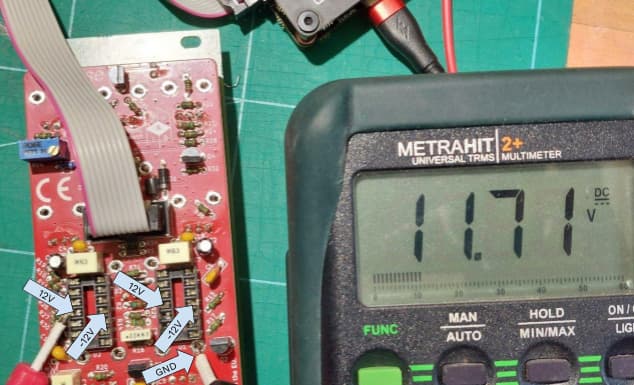
POWER CHECK
At this point we will be doing a quick smoke and voltage check.
Plug power PCB to your power supply and use a multimeter to make sure you get the right voltages in marked slots.
Place the ground probe (black) on one of the mechanical legs of any of the potentiometers, then test the center pins (4th from top or bottom) of the IC sockets. The multimeter should show +12V on the left pin and -12V on the right pin for both IC sockets.
ICs 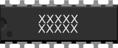
Place the ICs (Integrated Circuit, "Chip") in their respective sockets taking note of their orientation – the notch on one of the short sides (or the dot on the top) of the IC must match that of the socket and silkscreen. You can wipe the IC legs with alcohol or contact spray if you have that. Due to shelving they might have some oxidation. The legs are also likely to be too spread out to fit nicely into the sockets, so it will help to hold the IC against a flat surface (e.g. a tabletop) and gently bend both rows inwards a bit until they fit the width of the socket.
| Qty | Value | Name on PCB |
|---|---|---|
| 2 | TL074 | U1, U2 |
You’re nearly at the end, but the next part is critical and takes a good bit of concentration. If you’re feeling a bit strained, a break would definitely help. Mechanical parts are really delicate and will need your full attention.
FRONT PANEL COMPONENTS MOUNTING TIPS:
Now we will proceed to mount mechanical parts to the panel. This part of the assembly is critical. Please take your time and read the following instructions carefully.
These components must not be soldered until they are placed on the PCB and fully attached to the front panel!!!
There are two reasons for this:
- The height of the panel components are not all the same. Because of this, if not attached properly before soldering, they will not stay properly seated against the panel. This might cause mechanical stress reducing their life expectancy and in the worst case cause them to break.
- It is very difficult to align the components to the holes if the panel is not positioned prior to soldering.
POTENTIOMETERS
Now place the potentiometer on the PCB but… don’t solder them yet!
- When placing RV1, verify the stand doesn’t touch the pads of R1 and R34.
- When placing RV8, verify the stand doesn’t touch the pads of Q6.
- When placing RV10, verify the stand doesn’t touch the pads of R20.
You can use the multimeter to check the continuity. To fix problems, you might want to do one or more of the following suggestions:
- Cut legs of resistors closer to the PCB.
- Bend stand-off legs of pots, so they are out of the way.
- Use Kapton or electrical tape to insulate.
| Qty | Type | Name on PCB |
|---|---|---|
| 6 | Single (3pin) 100kB | RV2, RV5, RV6, RV8, RV9, RV10 |
| 2 | Single (3pin) 1MA | RV3, RV7 |
| 1 | Single (3pin) 10kB | RV1 |
MINI-JACKS
Place the mini-jacks on the PCB ensuring they are on the side with the silkscreen. Don’t solder them until the front panel is in place with all nuts screwed to it. This way it’s easier to solder them in the right position. Keep in mind that the front panel holes are quite narrow and it is almost impossible to place it with all the components already soldered.
LED 
Place the LED into the main PCB minding its polarity, but don't solder it until the front panel is in place. This is the only way to solder it in the right position. The long leg is the positive (anode) lead.
| Qty | Type | Name on PCB |
|---|---|---|
| 1 | LED Red 3mm Flat Top | D4 |
FRONT PANEL
Attach the front panel adjusting the parts one by one if necessary until it fits. At this point a pair of fine tweezers can be helpful.
To Finish:
- Screw in the parts in this order: A) Mini-jacks B) Pots.
- Ensuring all of the above parts are flush with the panel and both PCB and panel are perfectly parallel. Then you can finally solder them, except the two casing brackets for each potentiometer!
- Fit the LED on the panel hole. Then solder it. You can fit it flush or let it stand out: up to your preference.
- Connect the power ribbon cable: The red wire (-12V) on the power ribbon cable corresponds to pin number one on the male power connector. The number one pin is indicated with a small triangle on the male power connector and a white line on the main PCB. A white or black line (or “-12v”) marked on your power bus normally indicates the corresponding pin.
- Test the module thoroughly, if there is something unexpected, debug and fix before proceeding.
- Solder the potentiometer casing brackets in place to give them more stability.
- Put the knobs on the potentiometers. The Tuning knob is the larger one. The three gray knobs go on the three top potentiometers (LFO)…
CONGRATULATIONS!
You have built your Kit. It’s time to play around. Then, take it out of the rack again to tune it.
TUNING THE 1 VOLT PER OCTAVE SPREAD
- First set the tuning knob on the front to a center position.
- Connect a 1 Volt per octave CV source to the input labeled 1V/Oct.
- Play an octave on the input.
- Using a tiny screwdriver, set the trimmer RV4. This trimmer sets the spread of the tuning, not the tuning itself.
- You can use an app or a guitar tuner to help check the octave spread. Ignore the pitch at this point! Just make sure that the octave input gives you an octave (double the base frequency) on the output. Turning RV4 will change the pitch of both notes of the octave and the distance between them at the same time. Once you see that the higher note is twice the frequency of the lower note, you have successfully tuned Ilse.
Done. The tuning itself (setting the A to 440Hz) is done using the large tuning knob on the front.
PCB back side (you start with the back side)
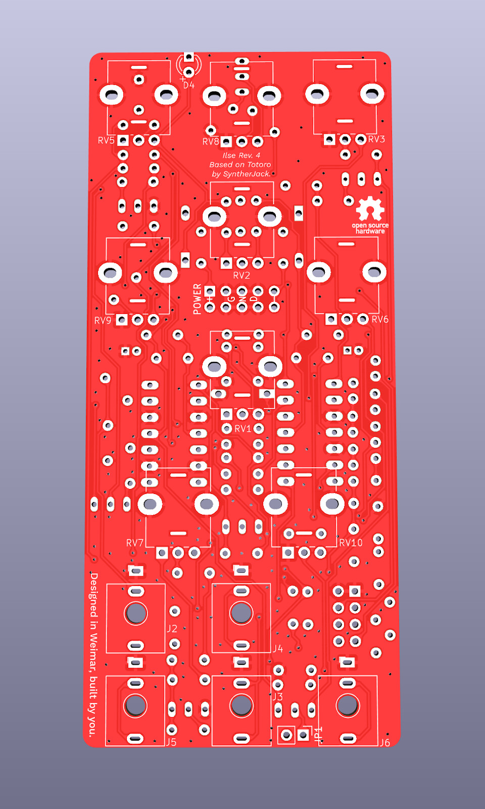
PCB front side
Many thanks to the fine folks at Befaco for kitting / distribution
and the template for this guide.
